


Im Frühjahr 2000 kaufte ich mir eine Diesellok Baureihe 216 mit Hochleistungs-Antrieb im modernen Epoche V Verkehrsrot, Märklin Nummer 37744. Dieses Modell hat ein eingebautes Soundmodul. In der Originalausführung liefert es zwei unterschiedliche Hörner, die mit den digitalen Fuktionstasten F2 und F3 (Märklin 6021) angesteuert werden.
Dieses Dokument beschreibt im Detail die Funktion der Soundplatine, die in
der erwähnten 216 (37744) und in der V160 des ersten Premium Startersets
(29845) eingebaut ist. Hier gibt es den Schaltplan, Soundaufnahmen zu hören
und Beschreibungen, wie man das Modul für weitere Sounds umbauen kann.
Technische Details
Nach der Demontage des Gehäuseoberteils sieht die Lok so aus:

Die lange Platine in der Abbildung ist das Soundmodul. Der Dekoder ist auf der Rückseite des Soundmoduls in einer Plastikhalterung eingeklippt. Die Soundmodul Platine ist zweilagig ausgeführt, die Kupferlage der Rückseite führt nur Masse, mit Ausnahme von zwei großen SMD Elektrolyt-Kondensatoren. Die Masseführung auf der Rückseite ist wohl notwendig, um hochfrequentes Übersprechen der Digitalsignale vom Dekoder (60902) zu unterbinden.
Der Digitaldekoder ist - so wie ich es sehe und zurückverfolgen kann - im Prinzip identisch mit dem 60902, bis auf Unterschiede bei den digitalen Funktionausgängen. Funktion F1 ist vorhanden, aber unbenutzt. Die Funktionen F2 und F3 sind mit dem Soundmodul verbunden, und die dafür benutzten Treibertransistoren sind schwächere Typen (kleinerer Kollektorstrom).
Hier ein Foto vom Dekoder: 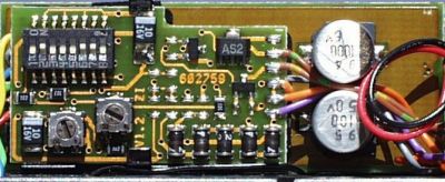
Und ein Foto vom Soundmodul: 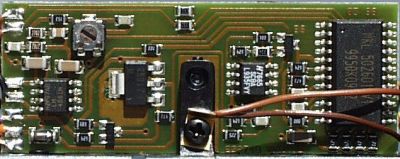
Die Größe des des Soundmoduls ist: Fläche 58 × 22 mm; Höhe 4 mm ohne Kondensatoren, mit ihnen sind es 14mm.
Die Leerlaufstromaufnahme ist 12 mA, d. h. wenn kein Sound aktiv ist. Wird
der Sound t3 (siehe Tabelle) aktiviert, werden ca. 140 mA bei maximaler
Lautstärke benötigt, bei Sound t2 ca. 110 mA. Spielt Sound t1, der Diesel,
fließen ca. 50 mA.
Schaltplan
Hier der Schaltplan des 602749 Soundmoduls:
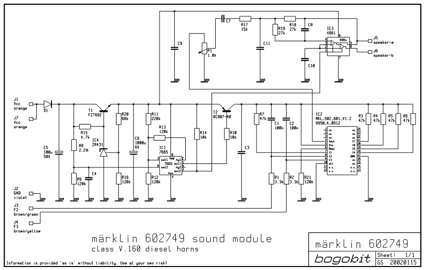
Klick auf das Bild, um ein hochauflösends GIF-Bild des
Schaltplans herunterzuladen.
Die Bestückung und Anschlußplan auf der Dekoderseite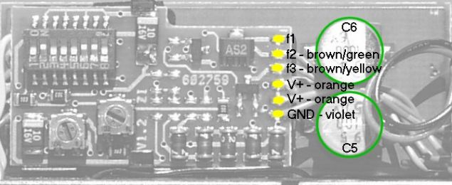
Bestückungsplan des Soundmoduls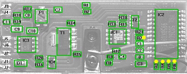
Die Funktion der Schaltung ist im Grunde einfach. Die Versorgungsspannung kommt von J1 (Vcc) via Diode D1 in den Pufferkondensator C5. Die Komponenten T1, R15, IC4, R20, R16 bilden den Spannungsregler. IC4 ist eine "einstellbare Zenerdiode". Sie passt die Kathodenspannung so an, dass am Controll-Pin 2,5 Volt anliegen. Der Spannungsteiler R20, R16 muss also 2.5 Volt liefern, und das tut er wenn am T1 Emitterausgang 3.9 Volt anliegen. IC1 ist ein Schwellschalter. Wenn der Spannungsteiler R8, R9 eine Spannung unterhalb 1.3 V zu Pin 6 abgibt, geht der Ausgangs-Pin 7 gegen Null, was den Audioverstärker (IC3) am Shutdown-Pin 1 aktiviert. Wenn dann die Versorgungsspannung zu sehr ansteigt, schaltet der Audioausgang ab. Ähnlich ist es mit Spannungsteiler R11, R12. Wenn der eine Spannung über 1.3 V zu Pin 3 liefert, geht der Ausgang Pin 1 nach unten, welches an T2 den Weg vom Emitter zum Kollektor schließen lässt, um den Soundchip (IC2) mit Spannung zu versorgen. Die Rückführung durch R13 erzeugt eine Hysterese wie bei einem Schmitt-Trigger.
IC2 ist Märklin's Sound-IC. Pin 4 ist der Audioausgang, der übrigens nicht tiefpass-gefiltert ist, sondern ein "Stufensignal" darstellt. Der Sound geht durch das Potentiometer P1, Entkopplungskondensator C7, durch den Tiefpass R17, C11, zum Verstärker IC3, der einen Brückenausgang zum Lautsprecher beinhaltet. Im Vergleich zu einem Single-ended Verstärker ist das Signal um den Faktor 4 (das sind 6 dB) verstärkt, und Elkos erübrigen sich. Die Komponenten R18, R19, C8 bilden einen weiteren Tiefpassfilter. Dies wir klar wenn man bedenkt, dass IC3 ein invertierender OP-Amp vom Eingangs-Pin 4 zum Ausgangs-Pin 5 ist.
Der Soundchip, IC2, gibt das Audiosignal an Pin 4 as, sobald er an einem der Eingänge t1 bis t7 getriggert wird, dies sind die Pins 7-9 und 18-21. Diese Pins sind intern auf High gezogen und werden durch eine Low-Spannung aktiviert, d. h. indem man den Eingang mit Masse verbindet. Zwei dieser Triggereingänge, t2 und t3, kann man mit dem "üblichen" Sound, oder mit einem "alternativen" Sound starten. Die Auswahl wird durch den Pin 10 "alt"-Eingang bestimmt. Bei der Standardschaltung ist er mit einem Null-Ohm Widerstand auf Low (Masse) gezogen. Der Pin ist intern auf High gelegt, wenn also der Null-Ohm Widerstand entfernt wird, schaltet das IC um und spielt die alternativen Sounds ab. Die anderen Triggereingänge spielen unabhängig vom "alt"-Eingang immer die gleichen Sounds. Wie Sie sehen werden fünf der sieben Eingänge nicht benutzt, diese sind extern mit 47k Widerständen (R3 bis R7) auf High gelegt. Wären diese Widerstände nicht mehr vorhanden würde die Schaltung weiterhin funktionieren. Alle Sounds, inklusive der nicht in dieser Lok benutzten, sind unten in der Tabelle mit Hörbeispielen aufgelistet. Wenn Sie schnell überprüfen möchten, welcher Sound in Ihren eigenen Modul möglich ist, halten Sie einfach einen normalen Widerstand mit etwa 3k - 22k an einem Ende mit den Fingern, und mit den anderen Ende berühren sie den entsprechenden Pin von IC2 oder ein gleichwertiges Lötpad der entsprechenden Pull-Up Widerstände. Diese Stellen sind mit den gelben Punkten auf dem Bestückungsplan gekennzeichnet. Ihre Körperkapazität reicht aus, um den gewünschten Pin des Soundchips auf Low zu ziehen. Selbstverständlich muss die Lok auf einer stromführenden Schiene stehen.
Die verbundenen Eingangs-Pins 8 und 9 sind über die Widerstände
R1 / R2 (je 3,3 k) mit den Dekoderfunktionsausgängen verbunden. Ein
Kondensator zu Vcc, C1 / C2, der filtert möglicherweise auftretende
Spannungsspitzen, die die Triggerspannung auf der Zuleitung verfälscht
oder beeinflusst. Widerstand R21 legt die Abtastrate (also die
Wiedergabegeschwindigkeit) fest. Niedrigere Werte des Wiederstands erhöhen die
Abtastrate und alle Sounds bekommen eine höhere Tonfrequenz und
Abspielgeschwindigkeit. Es ist so als ob Sie die Geschwindigkeit eines
Schallplattenspielers erhöhen. Audiobeispiele zeigen, dass Märklin
diesen Trick auch benutzt, um eigentlich identische Sounds mit einem Soundmodul
für verschiedene Lokmodelle anzubieten; hören Sie sich die folgenden
Beispiele an.
Hörbeispiele
Die folgende Tabelle listet alle gespeicherten Sounds des Sound-ICs mit der Beschriftung MKL 502 601 V1.2 auf. Die Auflistung erfolgt in der Reihenfolge der auslösenden Eingangspins. Die Soundbeispiele liegen im WAV-Format vor. Sie sind entweder von mir selbst aufgenommen, oder von Märklins Webseite.
Die Sounds von der Baureihe 218 sind t2, aktiviert mit Funktion F2, und t3, aktiviert mit Funktion F3, mit alt=low. Das F7 Horn auf t2 mit alt=high spielt ein kurzes oder langes Horn, wechselweise mit jeder Auslösung.
| Eingang | Sound | Abtastrate | Märklin WAV | mein WAV | Modus | Märklin Modell | Märklin Nummer |
|---|---|---|---|---|---|---|---|
| t1 | Dieselglocke | 8.4 kHz | V-GL_03.WAV | t1a.wav | fortlaufend | F7 | 37622, 37623, 26600 |
| t2 alt=low | Dieselhorn | 8.4 kHz | V-HO_11.WAV | t2a.wav | einmalig | class V160, 216 | 37743, 37744, 29845 |
| t3 alt=low | Dieselhorn | 8.4 kHz | V-HO_12.WAV | t3a.wav | einmalig | class V160, 216 | 37743, 37744, 29845 |
| t2 alt=high | Dieselhorn | 10.3 kHz | V-HO_11.WAV | t2b1.wav
t2b2.wav |
einmalig | F7 | 37622, 37623, 26600 |
| t3 alt=high | Dieselhorn | 10.3 kHz | - | t3b.wav | einmalig | F7 | 37622, 37623, 26600 |
| t4 | Dampfpfeife | 8.4 kHz | D-PF_04.WAV | t4a.wav | einmalig | S3/6, class 18.4 | 37184, 37186 |
| t5 | Dampfglocke | 7.7 kHz | D-GL_04.WAV | t5a.wav | einmalig | S3/6, class 18.4 | 37184, 37186 |
| t6 | Dieselhorn | 8.4 kHz | V-HO_07.WAV | t6a.wav | einmalig | class V188, V200 | 37284, 37803, 39821 |
| t7 | Dieselmotor | 10.5 kHz | V-MO_06.WAV | t7a.wav | unendlich | class V200 | 33803 |
Alle mein WAV-Aufnahmen sind von der 602749 Schaltung meiner BR216 gemacht worden. Die Schlussfolgerung, welche weiteren Soundloks dieses Sound-IC benutzen, basieren aus Studien der Märklin Produktbeschreibungen und Soundbeispielen (die "märklin WAV" in der Tabelle) und dem Vergleich mit meinen eigenen Aufnahmen.
Der Modus in der oberen Tabelle gibt an, wie die Funktion aktiviert wird. Generell, wenn Sie die Funktionstaste an ihrer Control Unit (6021) drücken, aktivieren Sie den Funktionsausgang des Dekoders; drücken Sie nochmal, deaktivieren Sie den Funktionsausgang. Die Sounds mit einmalig Modus spielen nur einmal, wenn die Funktionstaste betätigt wird. Bei Deaktivierung der Funktion passiert nichts. Sounds mit fortlaufend Modus spielen so lange wie die Funktion aktiv ist. Wird die Funktion deaktiviert, hört der Sound auf zu spielen.
Der Modus von Sound Nummer 7, dem Dieselmotor, ist unendlich. Wird die Funktion aktiviert, startet der Dieselmotor und läuft dann im Leerlauf. Deaktivieren der Funktion geht nicht! Der Sound spielt weiter. Wiederholtes Aktivieren der Funktion unterbricht den Dieselmotor und sofort startet der Motor mit der Startsequenz von vorne. Der einzige Weg um zwischen Leerlauf und laufendem Diesel zu wechseln, ist den Wert des Oszillatorwiderstandes an Pin 6 zu ändern, indem mit einem Transistor ein zweiter Widerstand parallel geschaltet wird. Dies erhöht die Abtastrate und somit die Tonhöhe des Diesels. Für Details dem Umbau, siehe das Kapitel unten "Dieselmotor anwerfen!".
Was passiert, wenn der Dieselmotor läuft und Sie ein Horn oder eine Glocke aktivieren? Der Dieselmotor wird für den Zeitraum unterbrochen und das IC geht auf Wiedergabe des des Hornes (Glocke). Wenn das Hornsignal zu Ende ist, spielt der Diesel wieder weiter. Genaugenommen reaktiviert sich der Diesel bei den meisten Diesel-Hupen und Glocken (t1, t2a, t3a, t3b, t6), aber nach dem kurzen F7 Dieselhorn und den Dampfsounds (t2b, t4, t5) bleibt er still! Die Stille nach den Dampfsounds kann durch ein Dieselhorn unterbrochen werden, welches den Dieselmotor wieder aktiviert. Die Frage ist nur ob es Sinn macht, einen Dampfsound mit einem Dieselmotorsound zu mischen.
Welche Möglichkeiten eröffnen sich da einem erfahrenen Hobbyeisenbahner mit Lötkolben?
Bitte werfen Sie eine Blick auf die folgenden Schaltpläne, sie zeigen die Verbindungen zwischen Dekoder, Motor und Soundmodul, vor und nach dem Umbau:
Auf der "Original Verdrahtung vor dem Umbau" können Sie sehen, dass Dekoder und Soundmodul mit folgenden vier Kabeln verbunden sind: f2 (braun/grün), f3 (braun/gelb), Vcc (orange), und Gnd (violett). Ein zweiter oranger Draht vom Dekoder geht zur vorderen Beleuchtung, ein zweiter oranger Draht vom Soundmodul geht zur hinteren Beleuchtung.
Um den Sound eines laufenden Dieselmotors zu bekommen, muss der Widerstand variiert werden, der die Abtastrate vorgibt. Dies ist der Widerstand R21, verbunden mit Pin 6 von IC2. Zu diesem schließen Sie parallel einen lichtempfindlichen Widerstand (LDR, light dependent resistor) an, der so entstehende Gesammtwiderstand verändert sich mit dem jeweiligen Lichteinfall auf dem LDR. Das Licht kommt von einer Glühbirne, die mit dem Motorausgang des Dekoders verbunden ist. Je höher die Motorspannung, um so schneller läuft der Sound, weil die Glühlampe den Widerstand des LDRs verändert. Mein Dank gilt RoB der dieses Schaltprinzip vorgeschlagen hat.
Beschreibung von Variante (1)
Für den Umbau nach Variante (1) beziehen Sie sich bitte auf den Schaltplan "Variante (1): Neue Schaltung mit diskreten Bauteilen und Verdrahtung nach dem Umbau":
Sie können jetzt mit der Funktion F1 den Diesel starten. Wie üblich können Sie mit F2 und F3 die zwei Hörner aktivieren. Da der Soundchip nur einen Soundausgang zum Verstärker-IC hat, verstummt der Dieselsound solange die Funktionen F2 oder F3 die Hörner spielen lassen.
Die Schaltung arbeitet wie folgt: Die Helligkeit der Lampe L91 ändert sich in Abhängigkeit von der Motorspannung. Je heller L91 ist, umso kleiner ist der Widerstand von R97. Um den minimalen Widerstand zu beschränken, muss R95 in Reihe geschaltet werden. T91 schließt gewöhnlich den Weg nach Masse, weil der Spannungsteiler R92, R93, R94 genug Spannung für die Transistorbasis liefert. R97 und R95 machen einen "Bypass" parallel zum Widerstand R21. Ein geringerer Wert von R95 ergibt eine höhere maximale Playbackrate, aber wenn R95 zu niedrig ist, hängt sich der Soundchip IC2 auf! Mit P91 kann der Anstieg der Wiedergaberate in Abhängigkeit von der Lokgeschwindigkeit eingestellt werden. Das bedeutet, wenn der Diesel zu schnell hochdreht, P91 nach oben drehen, wenn der Dieselsound zu langsam mit der Geschwindigkeit steigt, P91 zurückdrehen.
Problem ist, dass die Hörner, mit F2 oder F3 ausgelöst, ebenso mit der Abtastrate wiedergegeben werden und dadurch unnatürlich hoch klingen. Um dies zu verhindern, verbinden Sie die Funktionsausgänge mit je einer Diode (D91, D92) mit den Punkt zwischen R93 und R92. Dadurch fehlt T91 die Basisspannung und der LDR Bypass ist ausgeschaltet, somit können die Hörner mit der normalen Playbackrate abgespielt werden.
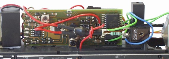
Dieses Bild zeigt die Decoderseite nach dem Dieselsound-Umbau. Beachten Sie,
dass fast alle zusätzlichen Bauteile an der rechten Kante
der Dekoderplatine angelötet sind.
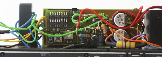
Dieses Bild zeigt die Soundkarte nach dem Dieselsound-Umbau. Beachten Sie
die Optokopplerkonstruktion, die mit dem roten Kabelknoten befestigt ist.
Hier ist ein Hörbeispiel nach dem erfolgreichen Umbau. Sie werden folgendes hören: zwei Hörner, den startenden Diesel, das Losfahren des Motors bis zur Höchstgeschwindigkeit mit entsprechend ansteigendem Dieselgeräusch, Verminderung der Geschwindigkeit, Abspielen der Hupe, und der Auslauf zum Stillstand mit Leerlauf den Dieselmotors. 602749di.mp3 (251 kB, 63 sekunden, 32 kb/s, mono).
Beschreibung von Variante (2)
Die Variante (2) unterscheidet sich von (1) darin, dass einige diskrete Bauteile entfernt wurden und dafür ein Microcontroller benutzt wird, und zwar ein Microchip PIC 12C508. Die Benutzung des Microcontrollers erlaubt weitere Eigenschaften:
Diese Variante wurde vorgeschlagen, programmiert, und getestet von Graham Guthrie. Sie sollten mit den PICs vertraut sein und ein PIC-Programmiergerät besitzen. Wenn nicht, benutzen Sie besser Variante (1).
Für den Umbau beziehen Sie sich bitte auf den Schaltplan "Variante (2): Neue Schaltung mit PIC Microprozessor und Verdrahtung nach dem Umbau":
Sie können jetzt mit der Funktion F1 den Diesel starten und stoppen. Das Stoppen erfolgt ziemlich plötzlich. Wie üblich sind mit F2 und F3 die zwei Hörner zu aktivieren. Die zuvor beschriebene genaue Zeitabstimmung über F2 oder F3 können Sie jetzt ignorieren, denn dies wird automatisch vom PIC gesteuert.
Die Schaltung arbeitet sonst wie die Variante (1). Wirklich neu ist nun, dass der PIC die Funktionen F1, F2, und F3 überwacht. Er kann den LDR Bypass durch einen I/O Pin kontrollieren, der in einer open-collector-Konfiguration benutzt wird. Der PIC nimmt seine Versorgungsspannung vom Emitter des T1 und von der Dauermasse der Versorgungsspannung. Um den Diesel zu stoppen, muss der Eingang Pin 3 des IC1 nach Masse gezogen werden, welcher dann T2 abschaltet. Dies schaltet die Spannungsversorgung des Sound IC aus.
Sie machen sich Gedanken warum die Seite 602749 heißt - es ist die Ersatzteilnummer der Soundplatine. Hier sind ein paar weitere Ersatzteilnummern:
| Bauteil | Nummer |
|---|---|
| Soundkarte | 602749 |
| Lautsprecher | 508600 |
| Lautsprecherbox | 207648 |
| Lautsprecherhalteclip | 207649 |
| Dekoder | 602765 |
| Dekoder Plastikhalter | 258820 |
Ich möchte mich bei all denen bedanken, die zu dieser Seite beigesteuert haben durch Diskussionen, Inhaltsüberprüfung, Fehlerberichte, und Beitrag weiterer Information! Mein besonderer Dank gilt Reinhard Bobzin für die ursprüngliche Übersetzung dieser Seite ins Deutsche. Die Übersetzung wurde von mir durchgesehen und geringfügig nachbearbeitet.